We accept payment by credit and debit cards (processed by PayPal) and PayPal account.

Shop Categories Applications and Information Laser Diodes
Laser Diodes
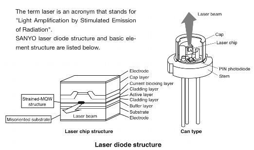
Anatomy of a Laser Diode
The structure of laser diodes depends on their type and manufacturer but a very common format for lasers up to ~500mW is 5.6mm can. For some higher power diodes this 'can' may be 'open'. Lower power laser diode cans often include a photodiode, used for automatic power control, these are usually excluded from higher power laser diodes.
The figure below is for a typical Sanyo laser diode.
Laser Diode Characteristics
Manufacturers quote 'Absolute Maximum Ratings' for laser diodes based on operation in production electronics where the maximum lifetime is required. Typically this will be in excess of 4-6000hrs and in projects it may be acceptable to exceed these ratings with a reduced life expectancy.
1. Absolute Power Ratings
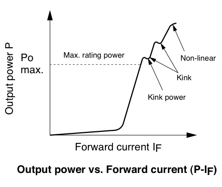
Light output power (Po)
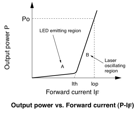
This is maximum allowable output during continuous operation. In the drive current light output characteristics shown in the figure below, there are no kinks or bends under this light output power.
For experimenters who wish to get the maximum power from a diode they will often wish to determine where the first 'Kink' occurs and drive the diode just below this level.
Reverse voltage (VR)
This is maximun allowable voltage with a reverse bias applied to the element. [Connecting a power supply 'the wrong way around' to the diode in excess of this value will damage or destroy the diode.]
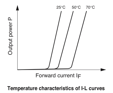
Ambient operating temperature (Topr)
This is the maximum ambient temperature in which the element can operate.
The level is defined by case temperature of the element. Since laser forward current (see below) increases with temperature at a set operating current the laser output will change with temperature.
2. Electrical and Optical Characteristics
Threshold current (Ith)
The P-IF curve distinguishes the LED light emitting region A from the laser oscillating region B, the current level that triggers laser oscillating is the threshold current.
Operating Current (Iop)
This is a current in the forward direction that is required to generate rated light output power.
Rated Optical Output Power (Po)
This is the manufacturer's rated output during continuous operation for the rated lifetime of the laser. Often experimenters will achieve, say a 50% increase in power with a 50% decrease in lifetime, - but since this may still be a 1000hrs it may be acceptable for the application - BUT see below for what happens if you go too high!.
COD (Catastrophic Optical Damage) Level
If current is flowing into the forward direction and output continues to rise following a kink or other deviation, then the laser eventually reaches facet breakdown (COD) level where the crystal at the facet melts due to the high optical density. Special care must be taken in the handling of red lasers because they may continue to oscillate with a low power of 2 to 3mW even after facet breakdown.
The life of a laser is significantly curtailed once the element is damaged, so
special care must be taken to avoid not only exceeding current when adjusting the output, but surge like static electricity as well.
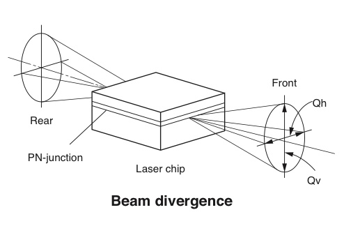
3. Beam Characteristics
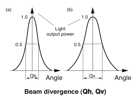
Beam divergence angle : Parallel (Qh), Perpendicular (Qv)
Light radiating from laser chip diverges as shown in the figure below. When the light distribution is measured in the parallel (X axis) and perpendicular (Y axis) directions with respect to the surface of the PN-junction on laser chip, (a) and (b) are shown in the figure on the lower right.